
When pressurized water (typically 50 to 80 PSI) escapes through an orifice in a copper or galvanized line buried under a concrete slab, the turbulent flow generates acoustic vibrations. Acoustic leak detection leverages seismic-grade ground microphones, contact transducers, and digital frequency analyzers to pin-point the exact rupture point within inches.
| Specification / Diagnostic Metric | Engineering Standard / Detail |
|---|---|
| Primary Technology | Piezoelectric ground contact sensors & listening discs |
| Operating Frequencies | 200 Hz to 2,500 Hz (custom notch filtering) |
| Depth Capability | Effective through 4 to 12 inches of reinforced slab & 3 ft of soil |
| Best Suited For | Cold water leaks, pressurized supply lines, zero-damage mapping |
| Accuracy Tolerance | ± 6 inches under standard residential concrete |
| Typical Diagnostic Time | 45 to 90 minutes for full perimeter & interior mapping |
Physics of Sub-Slab Acoustic Wave Propagation
Water under municipal pressure exiting a hairline fissure or pinhole leak undergoes rapid depressurization. This kinetic turbulence vibrates both the metal wall of the plumbing tube and the surrounding aggregate backfill. These micro-vibrations propagate through three distinct physical mediums:
- Internal Water Column Sound: Acoustic energy travels longitudinally along the water inside the pipe for dozens of feet in both directions.
- Pipe Wall Conduction: Mechanical sound waves travel through the rigid copper or PEX tubing, terminating at connected manifold fixtures, angle stops, and hose bibbs.
- Soil and Slab Radiation: Acoustic frequencies radiate upward through compacted pea gravel or native soil and resonate through the concrete foundation slab.
Acoustic detection technicians do not merely "listen" for rushing water. They deploy specialized equipment designed to isolate the high-frequency hiss of high-pressure orifice jetting from the low-frequency rumble of urban ambient traffic and electrical hums.
Acoustic Frequency Bands: What the Technician Hears
200 – 400 Hz: Low-frequency soil reverberation, common in water pooling around large breaks.
500 – 800 Hz: Copper wall resonance under normal domestic pressure (40–60 PSI).
1,000 – 2,200 Hz: High-frequency orifice jetting typical of pinhole pitting corrosion beneath concrete.
Specialized Acoustic Detection Instrumentation
Modern diagnostic specialists utilize an arsenal of acoustic devices rather than relying on a single microphone:
1. High-Mass Ground Microphones (Geophones)
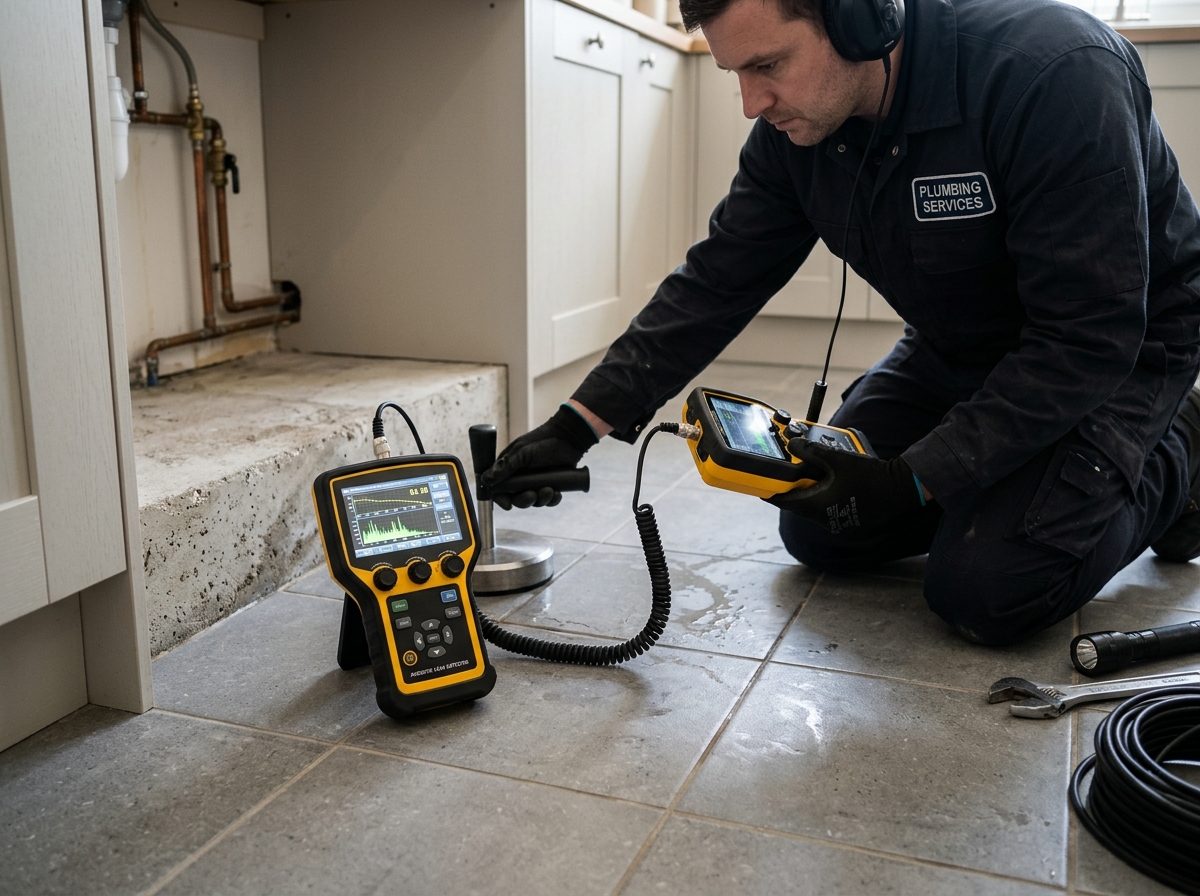
The primary tool for pinpointing leaks beneath living rooms, hallways, and slab perimeters is the seismic ground microphone. Encased in heavy brass or vulcanized housing, the geophone's mass decouples the sensor from room acoustics (such as running HVAC air or refrigerator compressors), ensuring that only physical floor vibrations reach the internal piezoelectric crystal.
2. Direct Pipe Contact Transducers
Before surveying floor surfaces, technicians attach contact probes directly to accessible pipe terminations—water heater inlets, hose bibbs, and shut-off valves. By comparing decibel levels across multiple fixture points, the operator isolates which plumbing run carries the strongest acoustic signature.
3. Digital Notch Filters and Spectrum Analyzers
Modern acoustic consoles feature active band-pass filtering. By notching out 60 Hz electrical mains noise and frequencies below 300 Hz (HVAC and traffic), the technician isolates the distinct 800 Hz–1,500 Hz frequency window characteristic of high-velocity water jetting against subterranean soil.
Why Acoustic Detection is Mandatory for Cold Water Leaks
While infrared thermal imaging provides instant visual identification for hot water line ruptures by highlighting thermal conduction blooms on flooring, cold water slab leaks are thermally invisible in ambient conditions. Ambient municipal water (60°F–70°F) provides almost zero thermal contrast against an air-conditioned concrete slab at 68°F–72°F.
Acoustic methodology remains the industry gold standard and definitive protocol for isolating cold supply line ruptures without breaking a single square foot of tile, hardwood, or structural concrete.
Diagnostic Correlation: Combining Acoustic and Electronic Profiling
Professional slab leak detection is never an isolated test. Acoustic confirmation represents Phase 3 of a standardized diagnostic sequence:
- Phase 1: Hydrostatic Isolation: Confirming pressure drop across isolated hot vs. cold supply manifolds using calibrated test gauges.
- Phase 2: Electromagnetic Pipe Tracing: Inducing a low-frequency radio signal onto the copper line to map its exact physical path beneath the foundation.
- Phase 3: Acoustic Triangulation: Moving the ground geophone in 12-inch grid intervals directly along the mapped pipe centerline to locate the peak decibel reading.